Skip to content

Usage Guide

Computer Set Up

  • Scan into the RPL with your PennCard and sit at an available computer.
    • If you are not trained, Get Training. If you lost access,  Get Access.
    • Each Laser and Computer have matching tags.
    • If you see an “Out of Order” sign on one of the lasers, do not use it.
  • Login to the computer using your SEAS account.
    • The exhaust system should automatically turn on if it was not already running when you entered the room.
      • If it is not, please notify the staff member at the desk, or email 
    • Place your material near you. If you need to order material, click here.

Convert .SLDPRT to .DWG

You cannot send files directly to the lasers from SolidWorks, but must pass them through an intermediate program (DraftSight). You should not be doing CAD work on the laser computers, this step comes BEFORE entering the RPL at all.

  • With your part file open, select File > Save As, change the type to DWG (*.dwg), name your file, and click Save.
  • If you have sketch entities that you would like to show up in the DWG, under Export, change to “Annotation Views” and make sure that you are oriented normal to the face you would like to cut.
  • If you have no sketch (2D) entities that you want to show up in the DWG, under Export, change to Faces / loops / edges, click on the face that you wish to laser cut, and click the green check mark.
  • Your sketch should appear in the DWG once you click the green check mark. When using “Annotation Views” your exact perspective in the SolidWorks window is converted to a DWG. That is why it is important to have a normal perspective when exporting under “Annotation Views.”
  • Optionally remove extraneous entities as desired, then click Save.

Prepare .DGW File in DraftSight

  • OPEN your .DWG file in DraftSight 2015 (Available in most MEAM labs).
  • To set how the laser will treat your geometry, you need to change the line colors. Do this by selecting a line, then choosing a color from the drop-down menu in the toolbar. Note that everything that is the same color will be treated similarly by the laser cutter (including the WHITE border – i.e. don’t leave your parts white!). The standard colors are:
    • RED – vector cutting (lines that you want to cut all the way though)
    • YELLOW – vector etching (lines that should be etched into your part)
    • GREEN – raster etching (areas that should be etched into your part)
    • CYAN – bounding box (lines to help position your stock, but won’t be cut)
  • To set up a raster etch field, see the Defining Raster Etch Areas section below. You cannot simply color the lines green.
  • Once done, select all lines and define their line thickness as 0.05.

Configure Laser Settings

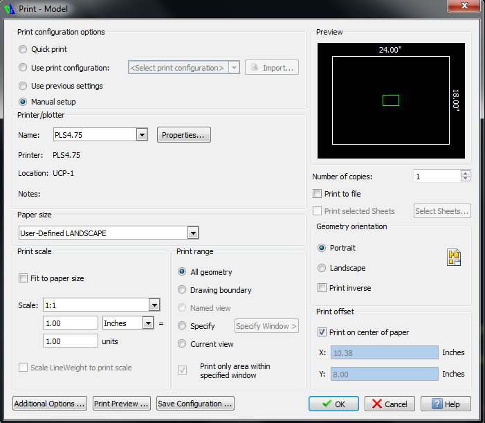
  • In DraftSight, select File>Print. The following window will appear:

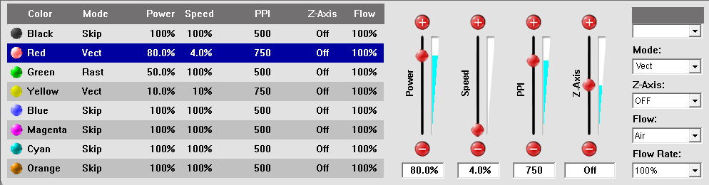
First, you will assign Parameters to each of the colors used in your file. In the “Printer/Plotter” section choose PLS4.75 from the dropdown menu as shown. Next, click the “Properties” button beside it.

  • Then set the “Power”, “Speed”, and “PPI” for each color depending on the material type and thickness (see Cutting Parameters)
  • Click “SET” and “OK” when complete. It should look something like this (these are the parameters for 1/8″ acrylic):

  • Make sure the rest of your settings in the print window appear as they do in the previous picture
    • For “Print Configuration Options“, choose “Manual Setup“.
    • Make sure “PLS4.75” is selected as the “Printer/Plotter“.
    • In the “Print Scale” section, make sure “Fit to paper size” is turned OFF, choose appropriate units (in or mm), and set the units to be 1.00 to 1.00.
    • For “Print Range, click “All Geometry“.
    • For “Print Offset“, click “Print on center of page“.
  • Click the “Print” button to send the file to the laser cutter. (note – you can send your file while another job is being cut, it will simply place it next in the queue.)
  • Click the Print button to send file to the ULS Control Panel.

NOTE: On the laser cutters, the jobs are stored on the computer, rather than on the machine, and we must open another software to actually start the job (ULS).

ULS Setup

  • Click the “show hidden icons” tab on the bottom-right of the computer’s task bar.
  • Click on the red icon to open the ULS Control Panel.
  • You should see your part to be cut in the field.
  • If you don’t see the colors that you specified, it is because vector cutting will only work if the weight of the line set to the minimum (0.05).
    • If needed, go back to the DWG and change it.
    • There should be a thickness, or weight, drop down menu near the menu where you change the color.
  • WARNING: The ULS Control Panel has a lot of active keys that actually move the laser cutter head. Do not click anything on this window until you are instructed to during the following Laser Step.

Laser Setup

  • Open the top door of the laser bed.
  • Check the LCD screen, the name of your DWG file should be showing.
  • Navigate to and enter the Z menu on the LCD screen.
    • Use the arrow keys to lower the bed until you can fit your material inside without hitting the laser cone.
    • Place your material on the bed, it should lay flat on the honeycomb surface.
    • Check where on your material you would like to make your cuts. Note roughly the location based on the X and Y guides around the bed.
    • Make sure the laser cone will not hit your material when moving around the laser bed.
  • Close the top door of the laser bed.

ULS Control Panel 

  • Select the Relocate View tool in the control panel (this is a button with four arrows pointing out of the center, in the middle of the horizontally organized buttons)
    • This will move your part in the space of the bed. Select an appropriate space to make your cut
      • If using scrap, place your part in the smallest available space
      • If using an uncut piece of material, place your part close to an edge, to maximize remaining continuous surface area in both X and Y directions
    • If you are making multiples of the same part, select the Duplicate tool in the control panel. It is to the right of the Relocate View
      • Use the up and down arrows to increase the number of duplicate parts you will add in the X or Y directions respectively.
      • You can also adjust the spacing between parts as necessary, though the default gap is fine for most uses.
    • Select the Focus View tool in the control panel. It is to the left of the Relocate View This will allow you to position the laser over the bed space
      • When you move your cursor over the bed, you will see two crossing lines with the specific X and Y coordinates.
      • Clicking on a point moves the laser and creates a blue X inside a circle for where the laser cone is currently pointing.
      • Use these steps to ensure your part fits on your material (opening the laser bed will show a red dot for where the laser is pointing)
      • Then move the laser cone to a location easily accessible for focusing the bed height

Laser Cutter

  • Open the top door of the laser bed.
    • Pick up the focus tool (white tube with a black base) which are tied to the walls behind the laser and should be sitting on the back of the laser you are using, or one next to it.
    • Place the focus tool on the material black base down, with the notched side touching the side of the laser head body.
      • Select the Z setting and move the bed up or down at 10 thousands of an inch at a time (the middle digit after the decimal when setting Z).
      • Continue adjusting the bed height until the laser head body pushes the notch on the focus tool.
      • Remove the focus tool.
    • Close the top door of the laser bed.
  • Press the large green Play button on the machine to start your job.
  • Monitor your job to ensure the laser cutter is functioning properly
  • Once the laser has finished, and returned to the corner, open the laser bed and remove your material.

Congratulations on completing your part!

    • Log off of the computer, or print your next dwg file.
    • Place any remaining usable scrap in the appropriate location in the scrap cabinet.
    • Place any unusable parts in the trash cans.

Defining Raster Etch Areas

    • Select Draw>Hatch/Fill….
    • Change the “Pattern” drop-down box to SOLID.
    • In the Boundary Settings section, click Specify Entities. The Draw Hatch dialogue box will disappear.
      • You will need to click and drag to select all entities that bound hatched regions.
      • After you have selected all entities, hit Enter and the Hatch/Fill dialogue box will reappear.
      • Be careful, the color of the geometries used to define the hatch will persist after the hatching process. If these are red, the geometries will be cut through. To outline your hatch, make these lines yellow, otherwise make green.
    • Click OK and admire your hatched geometry.
  • One last step – to change the color to GREEN, click the hatched area to select it, then change the color.