Skip to content

Resources and Reference

Drill and Tap Chart (Inch)

Thread SizeTap Drill (75% Thread)Tap Drill (50% Thread)Clearance (Close)Clearance (Free)
0-80 UNF3/64 (0.0469″)55 (0.0520″)52 (0.0635″)50 (0.0700″)
2-56 UNC50 (0.0700″)49 (0.0730″)43 (0.0890″)41 (0.0960″)
2-64 UNF50 (0.0700″)48 (0.0760″)43 (0.0890″)41 (0.0960″)
4-40 UNC43 (0.0890″)41 (0.0960″)32 (0.1160″)30 (0.1285″)
4-48 UNF42 (0.0935″)40 (0.0980″)32 (0.1160″)30 (0.1285″)
6-32 UNC36 (0.1065″)32 (0.1160″)27 (0.1440″)25 (0.1495″)
6-40 UNF33 (0.1130″)31 (0.1200″)27 (0.1440″)25 (0.1495″)
8-32 UNC29 (0.1360″)27 (0.1440″)18 (0.1695″)16 (0.1770″)
8-36 UNF29 (0.1360″)26 (0.1470″)18 (0.1695″)16 (0.1770″)
10-24 UNC25 (0.1495″)20 (0.1610″)9 (0.1960″)7 (0.2010″)
10-32 UNF21 (0.1590″)18 (0.1695″)9 (0.1960″)7 (0.2010″)
12-24 UNC16 (0.1770″)12 (0.1890″)2 (0.2210″)I (0.2280″)
12-28 UNF14 (0.1820″)10 (0.1935″)2 (0.2210″)I (0.2280″)
1/4-20 UNC7 (0.2010″)7/32 (0.2188″)F (0.2570″)H (0.2660″)
1/4-28 UNF3 (0.2130″)1 (0.2280″)F (0.2570″)H (0.2660″)
5/16-18 UNCF (0.2570″)J (0.2770″)P (0.3230″)Q (0.3320″)
5/16-24 UNFI (0.2720″)9/32 (0.2812″)P (0.3230″)Q (0.3320″)
3/8-16 UNC5/16 (0.3125″)Q (0.3320″)W (0.3860″)X (0.3970″)
3/8-24 UNFQ (0.3320″)S (0.3480″)W (0.3860″)X (0.3970″)
1/2-13 UNC27/64 (0.4219″)29/64 (0.4531″)33/64 (0.5156″)17/32 (0.5312″)
1/2-20 UNF29/64 (0.4531″)15/32 (0.4688″)33/64 (0.5156″)17/32 (0.5312″)


Drill and Tap Chart (Metric)

Thread SizeTap Drill (75% Thread)Tap Drill (50% Thread)Clearance (Close)Clearance (Free)
M1.6×0.351.25 (55)1.35 (54)1.70 (51)1.75 (50)
M2x0.401.60 (52)1.75 (50)2.10 (45)2.20 (44)
M2.5×0.452.05 (46)2.20 (44)2.65 (37)2.75 (7/64)
M3x0.502.50 (39)2.70 (36)3.15 (1/8)3.30 (30)
M4x0.703.30 (30)3.50 (28)4.20 (19)4.40 (17)
M5x0.804.20 (19)4.50 (16)5.25 (5)5.50 (7/32)
M6x1.005.00 (8)5.40 (4)6.30 (E)6.60 (G)
M6x0.755.25 (4)5.50 (7/32)6.30 (E)6.60 (G)
M7x1.006.00 (B)6.40 (E)7.40 (L)7.70 (N)
M7x0.756.25 (D)6.50 (F)7.40 (L)7.70 (N)
M8x1.256.80 (H)7.20 (J)8.40 (Q)8.80 (S)
M8x1.007.00 (J)7.40 (L)8.40 (Q)8.80 (S)
M10x1.508.50 (R)9.00 (T)10.50 (Z)11.00 (7/16)
M10x1.258.80 (11/32)9.20 (23/64)10.50 (Z)11.00 (7/16)
M12x1.7510.30 (13/32)10.90 (27/64)12.60 (0.5156″)13.20 (33/64)
M12x1.5010.50 (Z)11.00 (7/16)12.60 (1/2)13.20 (33/64)
M14x2.0012.10 (15/32)12.70 (1/2)14.75 (37/64)15.50 (39/64)
M14x1.5012.50 (1/2)13.00 (33/64)14.75 (37/64)15.50 (39/64)


.DXF -> .PT4 Conversion

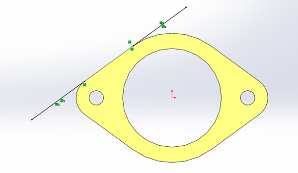
  1. Make sure your drawing is fully defined. No discontinuities! Computers don’t like dividing by zero. Also, include your Lead In/Out for your part.
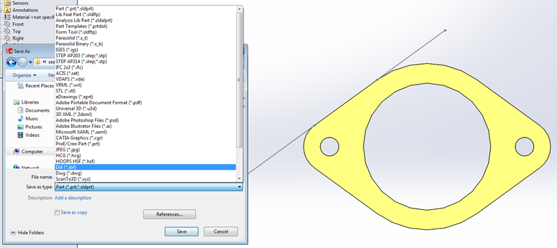
  2. Save your part as DXF
  3. Just like when you learned how to laser cut in MEAM 101, choose the face you are interested in.

Note: In order to include your Lead In/Out save the file by using the Annotation View that is associated with the geometry you are interested in.

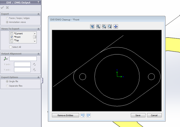
Note: You may encounter a problem with text on your exported dxf file. Solidworks 2013 appends an “instructional use only” text block on top of exported .dxf files. This can cause an error when establishing tool paths. If this is the case, delete the text in 2D Editor, OR chain the path you want to program and avoid clicking near the text block.

  1. Now open the most user friendly, ergonomically designed interface and software of the century: ProtoTRAK PT4 (On labeled computers at Towne 205- under the MEAM folder)

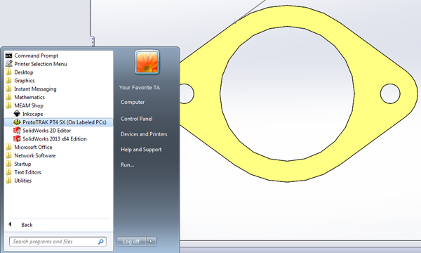
Note: Make sure you familiarize yourself with the Keyboard shortcuts…they will make your life easier

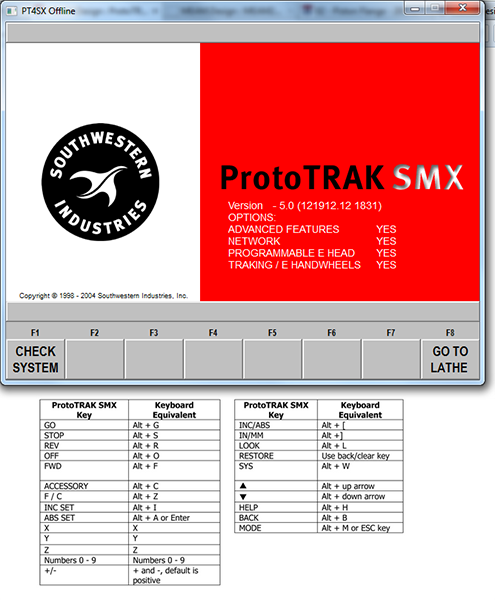
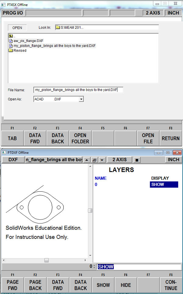
  1. Open your newly converted DXF file. To do so, select “alt+m” on the ProtoTRAK software. You will be presented with a series of new menu items at the bottom of the software. Select “PROG IN/OUT”, then “OPEN”, select open as “.DXF”, and navigate to and double click your file. Then select “CONTINUE”.
  2. Choose the Gap value (you probably won’t be changing this)
  3. Select your absolute zero. Be smart about this – let the drawings tell you the location of the absolute zero. After this, when prompted to “add lines”, simply click on “CONTINUE”.